Transforming a Failing Sidewalk with a Heavy-Duty Grid System
- DreamDen AI Editorial Team
- Nov 11, 2025
- 11 min read
A structurally weak, weed-ridden sidewalk can be rebuilt into a durable, low-maintenance surface using a cellular grid reinforcement system over a compacted gravel base. This guide consolidates the complete process from site evaluation and excavation through compaction, grid installation, aggregate infill, edging, and final detailing. It preserves the technical steps and measurements described in the source material while organizing them into a clear, repeatable workflow for driveways and walkable vehicular areas.
Overview: Why Use a Grid System Over Gravel
A plastic cellular grid system, when installed over a well-compacted, free-draining base and filled with angular aggregate, provides:
High load capacity: With properly graded aggregate compacted within the cells, the system can resist very high point loads (up to tens of thousands of pounds across the surface).
Aggregate confinement: The cells keep stone from migrating laterally, reducing rutting, washouts, and edge breakdown.
Drainage: The open, granular structure allows water to pass through, minimizing ponding and freeze-thaw damage.
Weed suppression: A continuous, overlapped weed barrier under the base and grids blocks upward growth from soil below.
Serviceability: Sections can be lifted and re-seated if subgrade adjustments are ever required.
The case examined here covers a sidewalk that will also serve as a light-vehicular apron ahead of a garage. The approach includes subgrade correction, drainage improvement, weed suppression, and grid-reinforced aggregate surfacing.
Site Conditions and Goals
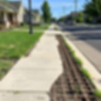
Existing conditions
Aging sidewalk with widespread vegetation growth through the surface.
Poor soil preparation in the original installation; no effective weed barrier.
Inadequate drainage; fines and organic material visible within the stone layer.
Transition to asphalt street requiring a clean, stable interface.
Project goals
Remove organics and fines contaminating the working surface.
Lower the interface at the asphalt edge by at least 4 inches to accept new base and surfacing.
Install a durable weed barrier (non-woven polypropylene landscaping fabric).
Build a compacted, free-draining crushed-stone base of approximately 2–3 inches beneath the grid.
Install a plastic cellular grid designed for driveways and sidewalks.
Fill the grid cells with 5/8-inch “minus” crushed stone and compact to a stable finish.
Add strong but simple edge restraint at a back retaining-wall interface to contain surface aggregate.
Produce a smooth, clean transition to the asphalt street with a tidy fabric trim line.
Equipment and Materials
Equipment
Compact track loader (CTL) or similar loader with quick-attach coupler.
Attachments:
30-inch general-purpose bucket for excavation and backfilling.
Auger attachment (used elsewhere on the site for garage footings; included here as context where heavy equipment logistics influence workflow).
200-lb vibratory plate compactor (gas powered).
Hand tamper for areas inaccessible to plate compactor.
String line and stakes for layout and straight-edge reference.
Rake(s) and 4×4 screed bar (or similar straightedge; a pallet or coupled lumber sections can be used to strike off wide areas).
Utility knife (and, if absent, a safe heat source to trim fabric flush in a pinch).
Materials
Non-woven polypropylene landscaping fabric (mold/rot resistant; high tear strength).
5/8-inch crushed gravel with fines (“5/8 minus”) for base and grid infill.
Landscaping fabric staples/spikes; long galvanized or similar corrosion-resistant.
Plastic driveway/sidewalk grid panels, approx. 24 in × 16 in × 2 in deep.
Pressure-treated 4×6 timber for a back edge restraint in one area.
1-inch rebar, 3-ft lengths for staking the timber edge (pre-drill with 1/2-inch bit).
Optional: corrosion-resistant landscape nails for pinning the first grid course at a critical
edge.
Step 1: Excavation and Height Adjustments
Target: Lower the front edge (asphalt interface) by at least 4 inches to make room for a compacted 2–3 inch gravel base plus 2-inch grid depth and stone cover.
Bucket geometry for control
Position the front edge of the loader bucket near vertical to shave and pull material in controlled slices. This allows finer control along the asphalt edge and reduces risk of undermining the asphalt.
Hand work at sensitive edges
Use a shovel to gently relieve soil directly against the asphalt. This prevents tearing the asphalt edge while the bulk of excavation proceeds by machine.
Bulk excavation
Remove contaminant layers: organic soil, mixed fines, and stone from the failed assembly.
Continue cutting until the design depth is achieved for the new system build-up (base + grid + cover).
High-end grading
At the top of the sidewalk or apron area, carry excavation to a uniform plane with gentle slope conforming to local drainage.
Precision here is not about laser-perfect elevation; the goal is a consistent thickness for the new base so compaction is even across the footprint.
Note: The same base-building logic applies even when heavy equipment is not available. The process can be completed with manual tools, though productivity will be lower.
Step 2: Subgrade Compaction
Objective: Densify the exposed subgrade (native soil and any retained sound material) before adding new base.
Initial compaction
Run the 200-lb plate compactor across the entire excavated area.
Make at least one pass in each direction to achieve uniform densification.
Address soft pockets
Identify and remove any visibly loose or pumping soil. Replace with crushed stone and compact.
This early compaction step limits future settlement and creates a uniform platform for the separation layer (landscape fabric) and base stone.
Step 3: Install the Weed-Barrier Layer
Objective: Prevent upward migration of organics and fines, suppress weed growth, and separate subgrade from the granular base.
Material
Use non-woven polypropylene landscaping fabric rated for high tear resistance and rot/mold resistance.
Layout and overlaps
Roll out the first course and align straight with the sidewalk centerline or a reference edge.
Overlap adjacent runs by 3–4 inches minimum.
At penetrations (e.g., sleeve tubes or foundations), cross-cut into quadrants and wrap snugly around the cylinder, ensuring the slit returns are overlapped under tension.
Anchorage
Pin the fabric perimeter and seams with long landscape staples or spikes.
Typical pattern: one fastener at ends and approximately every 1.5 meters (~5 ft) along seams and perimeter. Increase density along turns, transitions, and edges with expected traffic.
A continuous, well-overlapped, snug fabric layer blocks light and root intrusion while stabilizing the new granular base.
Step 4: Place and Rough-Grade the Crushed Stone Base
Target thickness: 2–3 inches of 5/8-inch minus crushed stone across the entire footprint beneath the grid system.
Stone selection
Choose 5/8-inch minus crushed stone. The “minus” denotes a gradation that includes fines, enabling tight compaction.
This material also drains efficiently, preventing trapped water beneath the grid.
Placement
Distribute stone over the fabric using the loader bucket. Avoid gouging or wrinkling the fabric.
Rough-spread to slightly above the target thickness.
Strike-off (screeding)
Use an 8-ft wide screed assembly (e.g., two 4×4s fastened together) to flatten high spots and pull material into lows.
Drag in perpendicular and diagonal directions until the surface is generally uniform.
Base thickness check
Use the asphalt edge as a reference and confirm the lowered subgrade provides room for base + grid (2 in) + surface cover (≈1/2 in after compaction), staying slightly below the asphalt elevation to prevent a bump.
Step 5: Compact the Stone Base
Goal: Achieve a dense, smooth platform for the grid. Dense base = less settlement and better load distribution.
Primary compaction
Run the plate compactor across the entire area twice: one pass in one direction, then 90° to that on the second pass.
Edge and obstacle areas
Where the plate cannot reach (e.g., around sleeve tubes and vertical impediments), switch to a hand tamper.
Ensure tight compaction against edges to avoid soft perimeters that can ravel later.
Re-screed if necessary
After compaction, use the straightedge to check for waves or low spots. Add or shave small amounts of stone and recompact as needed.
The result should be a firm, smooth base with no visible movement under foot traffic.
Step 6: Establish Straight Reference Lines for Grid Layout
Purpose: Ensure long runs of grid panels install straight and square, avoiding cumulative drift that shows at edges and seams.
Set stakes at control points
Drive stakes at both sides of the layout, using permanent elements (e.g., foundations) as references.
Pull two string lines, each 60 cm (about 24 inches) from the center of the reference foundation or edge, to define overall 20 ft (~6 m) width.
Verify parallelism
Confirm the two strings are parallel. Measure cross widths at intervals to keep cumulative error under control.
These reference lines guide the first rows and lock alignment for the entire field.
Step 7: Grid System Specifications and Preparation
Product characteristics
Panel size: 24 in × 16 in sections.
Cell depth: 2 inches.
Material: 100% recycled plastic.
Interlocking edges designed for quick mechanical connection across rows and columns.
Engineered for heavy-duty use; when filled with compacted aggregate, the surface can support up to ~88,000 lb of load across the system.
Packaging/coverage
Panels are supplied in packages ranging from 35 sq ft up to ~5,000 sq ft, suitable for anything from small pads to large driveways.
The installation addressed here includes ~825 sq ft at the front and an additional ~35 sq ft section at the back.
Step 8: Grid Installation Technique
Best practice: Build complete rows, then interlock rows together. This reduces fighting panel alignment and speeds up work.
Start against the reference line
Align the long edge of the first row with the string line.
Snap each panel into the previous one per the manufacturer’s connection pattern.
Row-by-row approach
Assemble a full row separately.
Assemble the second row separately.
Bring the full second row into engagement with the first and lock them together.
Repeat for subsequent rows, maintaining alignment with the strings.
Pinning the leading edge (optional but recommended)
At the front interface (asphalt edge or primary approach), pin the first course using landscape spikes to prevent drift while dumping stone.
This is especially helpful if filling by loader.
Continue to the back section
In secondary areas (e.g., a small rear bay where an additional vehicle may park), repeat the layout and installation with appropriately sized packages.
The goal is a fully interconnected, dimensionally consistent grid mat covering the entire footprint.
Step 9: Edge Restraint at a Retaining Interface (Timber + Rebar)
Where the grid abuts a small retaining wall or fence line and there is a risk of surface aggregate spillage, a simple restrained edge is useful.
Timber selection
Use pressure-treated 4×6 lumber as a low curb or edge beam.
Rebar stakes
Cut 1-inch rebar into 3-ft stakes.
Pre-drill the timber ends with a 1/2-inch bit to guide the rebar and reduce splitting.
Drive the rebar vertically with a sledgehammer through the pre-drilled holes and into the subgrade, anchoring the timber.
Placement
Set the timber so it forms a flush or slightly raised containment against the grid edge, preventing stone roll-out while allowing drainage.
This restraint method reinforces the back edge with minimal visual bulk and robust hold-down.
Step 10: Filling the Grid Cells with 5/8-Minus Stone
Objective: Fill to slightly above cell height before compaction so the final, compacted surface hides the grid.
Bulk placement
Back the loader over prepared areas and dump into the cells.
Avoid excessive downward pressure with the bucket to prevent popping panels loose. If a panel shifts, re-seat it immediately.
Rough raking
Use landscape rakes to pull stone across the surface to a uniform height.
Aim high: a small excess (above the 2-inch cell height) is necessary to account for settlement during compaction and to keep the grid invisible.
Screeding
Use the 4×4 straightedge assembly (or similar wide tool) to smooth the top layer, knocking down ridges and filling low spots across the full width.
Loader finesse
With practice, use the bucket to gently “float” and level broader areas, minimizing hand raking while maintaining cell fill and avoiding panel displacement.
The target before compaction is a continuous stone blanket with no visible grid ribs.
Step 11: Final Compaction of the Filled Grid
Passes and outcome
Primary compaction
Run the plate compactor over the entire filled grid twice, as done for the base: once in each principal direction.
Use a hand tamper to densify edges and around obstructions.
Surface check
After compaction, evaluate the surface. If grid ribs reappear, there is insufficient cover.
Add additional ~1/2 inch of stone across thin areas and recompact until the grid is fully concealed under a tight, stable stone surface.
Ordering noteCompaction reduces volume significantly. Even with a planned base and cover, additional crushed stone may be required to achieve final cover. Plan for extra tonnage beyond the calculated volume—e.g., an additional ~10 ft³ (or more depending on area) to top up after settlement. Ordering a buffer supply prevents delays.
Step 12: Finishing the Asphalt Interface and
Trimming Fabric
Edge clean-up
Pull back any loose stone from the asphalt edge to reveal a crisp transition.
Trim excess fabric flush with a sharp utility knife.
Alternate trim method
If a blade is unavailable and local regulations allow, carefully singe stray fabric fibers with a flame to seal the edge (use extreme caution, observe fire safety, and avoid damaging adjacent materials).
A clean termination against asphalt improves appearance and prevents fabric wicking at the edge.
Material Quantities and Logistics
Base and infill stone: The initial estimate for the front project section was 12 cubic yards of 5/8 minus. During installation and after compaction, additional stone was required to provide final cover across the grid.
Grid footprint: Approximately 825 sq ft across the main sidewalk/apron, plus ~35 sq ft in a rear-parking pocket.
Fabric: Sufficient rolls to cover the entire area with 3–4 in overlaps; staples every ~5 ft along seams and perimeters.
Rebar and timber: As required for the edge restraint in the rear section; 1-inch rebar, 3-ft lengths, through a pressure-treated 4×6 beam.
Planning for an overage in aggregate and having additional grid panels on hand (or quick access to more) simplifies field adjustments.
Compaction and Performance Notes
Why 5/8 minus: The presence of fines allows aggregate to densify under vibration, locking particles together within the grid cells. “Clean” stone without fines does not compact as tightly and can remain mobile in the cells.
Multiple passes: Two orthogonal passes of a 200-lb plate compactor on both the base and the filled grid produce a firm, unified surface.
Obstruction detailing: Areas around sleeve tubes and edges must be hand-tamped to prevent local softness that can telegraph through the surface.
Workflow Tips and Quality Controls
String lines: Maintain straightness over long runs; periodic checks at offsets keep the field square to references.
Panel sequencing: Building complete rows and then interlocking rows prevents cumulative misalignment and speeds installation.
Front-row pinning: Pinning the first course controls shift during heavy bucket work.
Overfill before compaction: Always target a slightly high surface prior to compaction so the finished surface hides the grid.
Expect top-up: Plan to add ~1/2 inch of aggregate after initial compaction.
Edge restraint where needed: Provide simple but strong containment against features like small retaining walls or fence lines.
Safety and Handling
PPE: Gloves, eye protection, hearing protection, and respirator/dust mask when handling aggregate and cutting or burning fabric edges.
Equipment operation: Maintain control near asphalt edges and structures; avoid undermining or impact damage.
Manual compaction: Use proper stance and technique to avoid strain, especially when hand-tamping in tight spots.
Heat trimming: If used, apply with care, in ventilated conditions, away from flammable materials.
Troubleshooting
Grids popping loose while filling
Reduce pressure from the bucket; use lighter lifts; re-seat and reconnect panels immediately.
Pin the leading course.
Visible grid after compaction
Add stone to insufficient areas and recompact.
Ensure fines are present in the mix; “minus” gradation is essential.
Soft edges
Augment with hand tamping; add additional infill; consider an edge restraint where traffic scours are expected.
Weed growth through finished surface
Typically indicates missing/insufficient overlaps in fabric or perforations at penetrations. Proper fabric overlap (3–4 in) and snug wraps around tubes prevent light and soil pathways.
Result: A Durable, Clean, and Drainable Surface
When executed in the sequence described:
Subgrade is corrected and compacted.
Weed barrier separates soil from base and blocks light.
Free-draining, compactable 5/8-minus stone forms a uniform base.
Interlocked plastic grids confine the infill and distribute loads.
Aggregate fill is compacted to a smooth, stable surface that conceals the cells.
Edges are contained and transitions are clean.
The finished sidewalk/apron is structurally sound, resists rutting and migration, drains well, and is protected against weed intrusion, with a crisp termination at the asphalt.
Specification Summary (At-a-Glance)
Excavation at asphalt: Lower ≈ 4 in to accommodate base + grid + cover.
Weed barrier: Non-woven polypropylene; 3–4 in overlaps; staples every ~5 ft and at ends.
Base course: 2–3 in of 5/8-in minus crushed stone; plate-compact twice.
Grid panels: 24 in × 16 in × 2 in deep; recycled plastic; interlocking.
Layout: String lines at 60 cm offsets each side to confirm ~20 ft overall width.
Infill: 5/8-in minus, slightly above cell height pre-compaction; compact twice; top up ~1/2 in if ribs are visible.
Edge restraint (selected areas): PT 4×6 timber pinned with 1-in rebar, 3-ft lengths.
Final trim: Clean asphalt interface; trim fabric flush.
Maintenance Considerations
Periodic sweeping/raking to redistribute any loose surface fines and maintain a level finish.
Top-up infill if local scouring or minor settlement occurs (rare when installation follows this guide).
Edge checks after the first season to confirm no migration at interfaces; install additional restraint if needed.
Conclusion
A failing, weed-infested sidewalk can be rebuilt into a durable, permeable, and visually clean surface by combining proper excavation, subgrade and base compaction, a robust weed barrier, and a heavy-duty plastic grid system filled with compacted 5/8-minus aggregate. Key performance factors include sufficient excavation at the asphalt edge, uniform base thickness, straight and locked grid rows, adequate overfill before compaction, and thoughtful edge restraint where aggregate might escape. The result is a strong, low-maintenance surface ready for pedestrian and light vehicular loads, with long-term resistance to rutting and weed incursion.